Skeletal Point Tracking Source
The Skeletal Point Tracking Source allows the joints of a skeleton to be controlled using tracked points from a marker-based tracking system. It can be used in conjunction with tracking drivers such as:
Setting up a skeletal point tracking source to control a skeleton
Section titled “Setting up a skeletal point tracking source to control a skeleton”- Set up a suitable tracking system and driver to receive tracked points in Disguise
- Create a rigged mesh with joints at each tracked marker position, export as FBX and select in a skeleton
- Under Hierarchy in the skeleton, click Create Reference Points to create a reference point for each joint
- Create a new SkeletalPointTrackingSource and set it as the skeleton’s tracking source
- In the tracking source editor, add points to link each tracked point to its corresponding reference point
- Points can be sorted into groups. If a point stops receiving tracking data, its position will be estimated based on a rigid body transform from other receiving points in the same groups
- Each point can also have an offset applied relative to the fixed point
- Adjust the Rejoin velocity limit under Advanced to change the speed at which points catch up with the tracked position when tracking is received again after being lost.
- Adjust the Min/Max point locations under Advanced to set bounds on the area in which tracked points are followed.
![]()
Using a skeletal point tracking source to track a deforming surface
Section titled “Using a skeletal point tracking source to track a deforming surface”The skeletal point tracking source is ideal for tracking a deforming surface. To do this:
- Create and rig a FBX skeletal mesh which matches your deforming surface. See below for tips on how to do so.
- Set up and track a skeleton using your skeletal mesh, following the steps above.
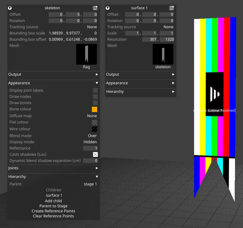
- Create a new surface, and select the deformable mesh which is named after the skeleton, NOT the original FBX mesh which is selected in the skeleton. The surface should now deform with the skeleton.
- Make the surface a child of the skeleton and zero out its position and rotation, so that the origins are aligned.
- Set the Skeleton Display mode under Appearance to Hidden if you just want to see the surface mesh.
- Use your surface for projection or other workflows as normal.
Preparing your skeletal mesh
Section titled “Preparing your skeletal mesh”To achieve optimal tracking of a deforming surface, it is crucial to set up the skeletal mesh as accurately as possible. Below are some tips for how to model and rig your mesh:
- Create a bone structure which follows the positions of the tracked point, with a hierarchy appropriate for the structure of the surface. There should be a joint aligning with each tracked point. It is ok to have additional joints which don’t correspond to tracked points at the top or bottom of the hierarchy, but it is not recommended to place untracked joints between tracked joints.
- The base layout of the skeleton should match an average/neutral pose of the real surface as closely as possible. One way to ensure this is by capturing the locations of the tracked points with the surface in place, loading these into your modelling software, and adjusting your joints to align exactly with the captured tracked points.
- The skeletal mesh should be exported with its base positioning fully captured in the layout, with a fully-zero pose. When loading the skeleton into Designer, you should see all zeros in the joint positions and rotations in the skeleton editor. If this is not the case, you may need to reset the bind pose and/or remove pose offsets and rotations in your modelling software.
- It is important to weight the vertices as accurately as possible to model the deformation of the surface as the tracked points move. The best way to do this will depend on the physical properties of the surface itself, however a good starting point is to ensure that all vertices adjacent to tracked points are fully weighted to the corresponding joint, so that they stick to the tracked point as it moves around. The remaining weightings should be applied roughly based on the distance to the corresponding joint. Note that auto-weighting algorithms often weight based on the distance to the bone rather than the joint, which can lead to the modelled surfaces diverging away from the tracking markers.
- Joints which are at the end of the hierarchy may not be able to extend along the length of the bone (e.g. to follow a stretching surface) since they do not have a bone beneath them. In this case it can be beneficial to add additional small ‘dummy’ bones at the end of the hierarchy, not weighted to any vertices. This will allow full control of the previous end joints.