Projectors
Projectors are the core authoring object in Mapping Matter. Each projector carries real specifications from the catalogue (Panasonic, Christie, Barco, and others) including throw ratio, lens shift and lumens. You position projectors in 3D, aim them, and see the resulting beam, image and coverage on the geometry in the scene.
Add a projector
Section titled “Add a projector”Click Projector in the viewport toolbar’s add cluster to open the projector library overlay. Browse by manufacturer, search by model, or filter by lumens and resolution.
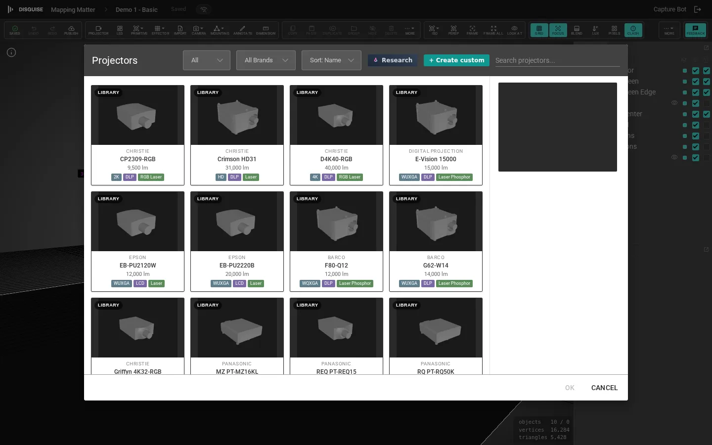
Double-click a projector to add it to the centre of the viewport. You can also drag a model from the library onto the scene tree.
If a catalogue entry has wrong specifications — incorrect throw ratio, missing lens, rated lumens that don’t match the datasheet — click the small flag icon on the projector card to send a targeted report to the Disguise team. The dialog pre-fills the model name and the suspect values, so the report comes through with the right context attached. The same flag is available on LED tile and truss library cards.
Aim the beam
Section titled “Aim the beam”A projector’s beam is aimed at its target point — a small handle in the viewport. Drag the target to point the beam; the projector rotates to face it. The aim can also be set numerically in the projector’s Properties panel.
To rotate the projector body independently of the aim, use the Rotate gizmo on the projector directly.
Focus simulation
Section titled “Focus simulation”Real projector lenses have a depth of field — surfaces nearer or farther than the focal plane look soft. Mapping Matter approximates this with a Focus overlay: surfaces that fall outside the projector’s focal depth are drawn with diagonal banding, with denser, brighter bands the further out of focus they are.
Toggle the simulation with the Focus button in the toolbar’s display cluster. Behind that button are three modes, set in Viewport settings (bottom Panels strip) under Focus Mode:
- Off — no overlay.
- Per Projector — only the selected projector contributes. Use this to read one fixture at a time when several beams overlap.
- All Projectors — every projector’s focus depth is overlaid simultaneously. Useful for catching surfaces that no projector resolves cleanly.
The two thresholds on the same panel control where the bands appear:
- Focus T1 — the tight in-focus tolerance, expressed as a fraction of the projector’s nominal throw distance. Surfaces within ±T1 are treated as fully sharp.
- Focus T2 — the broader “near focus” tolerance. Between T1 and T2 surfaces render with the lighter banding; beyond T2 they get the heavier banding.
Defaults (T1 = 0.10, T2 = 0.30) approximate a typical mid-range zoom. Tighten T1 to model a long-throw lens; widen it for a short-throw / UST head.
Edit a projector
Section titled “Edit a projector”Select a projector to expose its full Properties panel:
- Name — label shown in the scene tree.
- Position / Rotation — XYZ values in the active scene unit; matches the gizmo.
- Change Projector… — swaps the model, preserving position, orientation and aim.
- Lens — the active lens preset for the projector. Each preset carries its own throw-ratio and lens-shift ranges; selecting one applies the geometry.
- Resolution — the active SDI/HDMI mode for projectors that ship multiple supported resolutions (e.g. 16:9 1920 × 1080 vs 16:10 1920 × 1200 on the same panel). The dropdown is hidden when the catalogue lists a single native resolution. Picking a mode overrides the projector’s reported resolution everywhere — test pattern, projection width × height, the sidebar header — while the underlying library entry stays intact.
- Throw Ratio — image width as a multiple of throw distance. The field’s allowed range follows the active lens; the row turns yellow near the lens limit and red beyond it.
- Projection Distance — distance from the projector to the surface it’s aimed at. Accepts values below 1 m for ultra-short-throw lenses; the near plane of the frustum adapts so the image isn’t clipped on short throws.
- Lens Shift (%) — horizontal and vertical optical shift expressed as a percentage of the image extent (100% = half the image dimension, matching Barco/Christie conventions). The row colours the same way as throw ratio when out of range. Some lenses publish an asymmetric envelope (e.g. shift up 50%, shift down 30%) — the sliders honour the asymmetry. Lenses that publish a firmware-locked or no-shift envelope disable the sliders entirely; the optical offset baked into the lens (e.g. a UST lens’s large fixed upward offset) still applies.
- Brightness Factor (%) — scales output lumens between 1% and 200%, useful for derated or aged units.
- Visible / Locked / Powered — visibility, transform lock, and on/off state.
The Information collapsible shows derived geometry — Horizontal FOV, Vertical FOV and the equivalent Focal Length (computed for a 24 mm film height).
For projector identity (brand, model, lumens, native aspect ratio) the panel includes a read-only info box. When stacking is on, the box also shows Total Stack Lumens.
Projector image and test patterns
Section titled “Projector image and test patterns”The Projector Image collapsible controls what the projector outputs. Each option is an independent toggle — Border, Grid and Checkers can all be enabled at once, and any of them can sit over an assigned Image.
- Image — assign a still or video texture. Press space to play a video texture.
- Border — draw a coloured frame around the projected image. Set the colour with the swatch and the thickness as a percentage of the frustum.
- Grid — overlay a grid; set the cell count along the H and V axes (independent values, 0–8192).
- Checkers — overlay a black-and-white checkerboard; set the cell count along H and V (independent values, 0–8192).
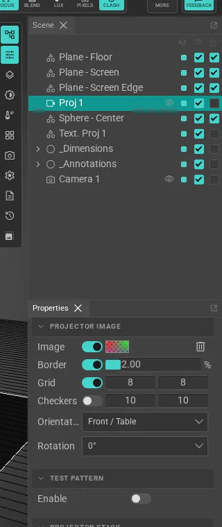
The Border / Grid / Checkerboard patterns are intentionally lightweight test patterns for verifying alignment and pixel density without needing a content file. Combine them with the Photometric analysis toggle to validate coverage as you align the rig.
Rear projection
Section titled “Rear projection”By default a projector only lights the front of each surface it hits — the side whose face normal points back toward the projector. For rear-projection screens (translucent screens lit from behind) that means the image lands on the wrong side of the geometry.
To enable rear projection, open the target surface’s Properties panel and change its material Side from Front to Back (rear-projection screen) or Double (lit from either side). Projectors aimed at the back of the surface then resolve and illuminate it as you’d expect. The same setting also controls back-side visibility in the viewport.
Use Double when one screen is shared between a stage projector and a rear unit; use Back when the screen is only ever lit from behind and the back-only face culling matches the physical install.
Stacking
Section titled “Stacking”Open the Projector Stack collapsible to overlay duplicate projectors at a single position for additional lumens:
- Add Dummy Projectors — slider, 1–20, the number of clones to add.
- Automatic Lumens Multiplication — when on, the read-only info box reports total stack lumens.
- Offset (X/Y/Z) — physical spacing between the stacked units.
Mirror
Section titled “Mirror”A projector can drive an attached mirror to fold its beam — useful for short-throw, snorkel and bounce configurations. Open the Mirror collapsible in the selected projector’s Properties panel and toggle Enabled. See Mirror for the full workflow.
Mounting on a truss
Section titled “Mounting on a truss”Projectors can be clamped to a truss with a per-instance clamp position, hang direction (below / above / left / right of the chord) and height offset. The Mounting collapsible in the Properties panel covers the cage toggle, clamp pickups, and the Ground tower / Flown truss / Existing truss quick-attach buttons. See Trusses & mounting for the full workflow.
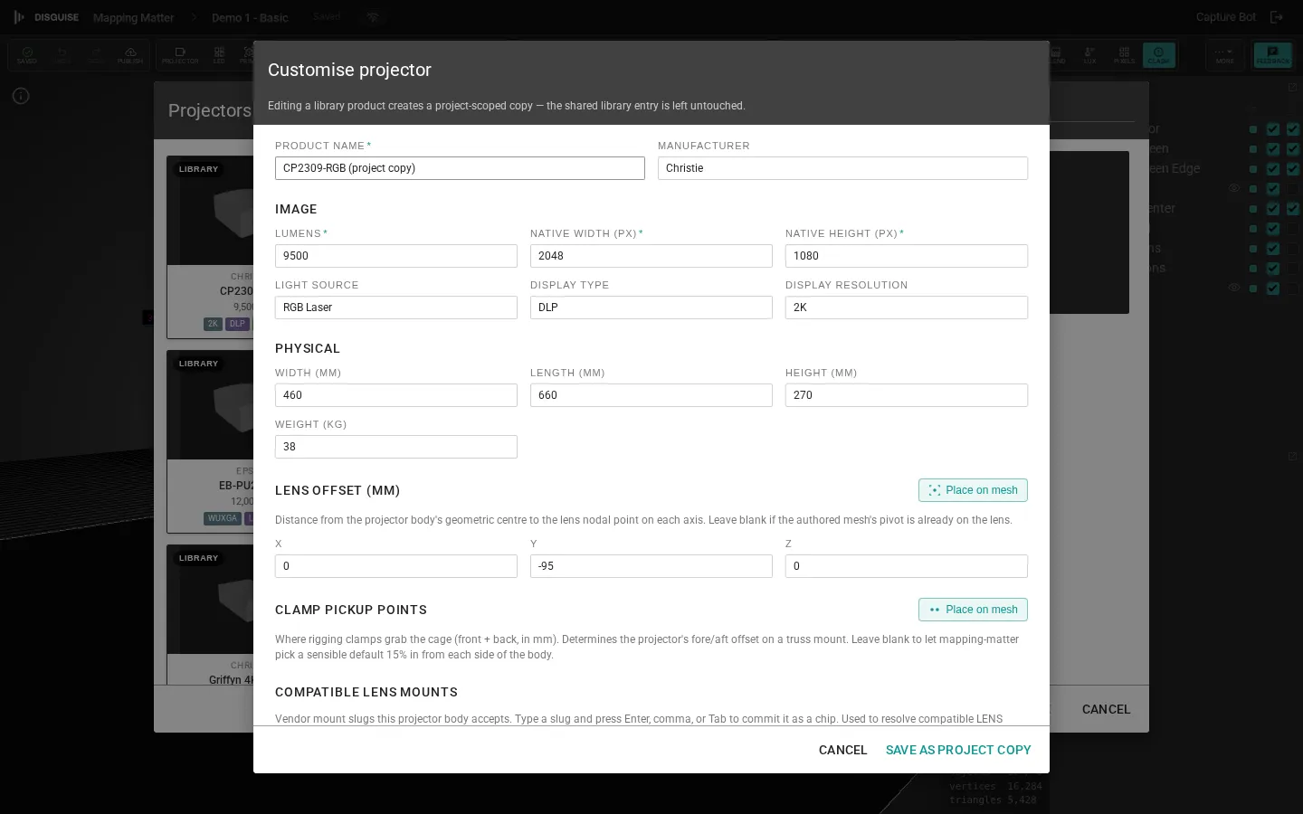
Custom projectors and the nodal-point editor
Section titled “Custom projectors and the nodal-point editor”If a projector model or lens you need is not in the catalogue, click Projector in the toolbar, then + Create custom at the top of the library overlay. The custom-product form asks for:
- Brand and model.
- Dimensions (mm) — width, length, height. Optional but used by the nodal-point editor to scale the body mesh.
- Body mesh — a
.glb,.fbx,.objor.daeupload. Converted to GLB client-side. - Lens offset (X/Y/Z) — where the lens nodal point sits relative to the mesh origin.
- Lenses — one or more lens presets, each with:
- Mount slug, part number, manufacturer.
- Optical offset — a fixed V/H beam offset baked into the lens, expressed as a percentage of image height (or half-height, per the convention dropdown — Christie uses half-height, DP/Epson/Sony use full-height).
- Adjustable shift envelope — the mode (motorised, manual, firmware-locked, or none), the envelope shape (rectangular or rhomboid), and asymmetric
v_up / v_down / h_left / h_rightpercentages. Firmware-locked and no-shift lenses disable the shift inputs but keep the fixed optical offset. - Throw-ratio range and a throw reference offset to mark where the lens’s published throw is measured from.
AI ghost-fill on create
Section titled “AI ghost-fill on create”As soon as you’ve typed both a manufacturer and a model into the create form, Mapping Matter fires a background AI research call and shows an AI suggestions ready banner at the top of the form. Click Apply all to fill every still-empty field with the suggested specs — user-typed values are never overwritten. The form’s lens name and lens-mount fields are also autocomplete-driven: typing into either pops a suggestion list pulled from the product DB (and falls back to a fresh AI lookup if there’s no DB match).
To place the nodal point visually rather than by typing offsets, upload a body mesh first, then click Place on mesh under “Lens offset (mm)”. The form panel switches to an embedded 3D view of your uploaded mesh with a teal gizmo at the current offset. Drag the gizmo onto the lens centre on the mesh, then click Save to write the new XYZ values back into the form. Click Cancel to keep the previous offset.
Saved custom projectors appear in the projector library under a “Project copies” group at the top, and behave identically to catalogue models in the rest of the editor. Each tile in that group has a delete affordance — confirm the prompt to remove the projector from the project library. Catalogue (manufacturer) rows are read-only and don’t show the delete button.
The create dialog only closes via Cancel or Escape; clicking outside it does nothing, so an accidental backdrop click can’t lose your edits.
Photometric and brightness analysis
Section titled “Photometric and brightness analysis”Once projectors are placed, see Viewport & analysis to validate luminance, coverage, and overlap.